What is AC electricity:
The easiest explanation of electricity is a water dam. Picture a dam with a pipe at the bottom letting water out. The higher the dam the more pressure there is at the bottom of the dam the water comes out faster because it is under more pressure. So, pressure is Voltage they are one in the same.
Increase the size of the pipe at the bottom of the dam and you increase the amount of water coming out or current flow. Current flow is Amperage.
Together you arrive at gallons an hour or Watts. Reduce the height of the dam and you reduce the pressure or voltage, and you reduce the current flow. Make the size of the pipe bigger you can adjust for the drop in dam height and increase the current flow. These two factors equate to gallons per hour VOLTS X AMPS = WATTS.
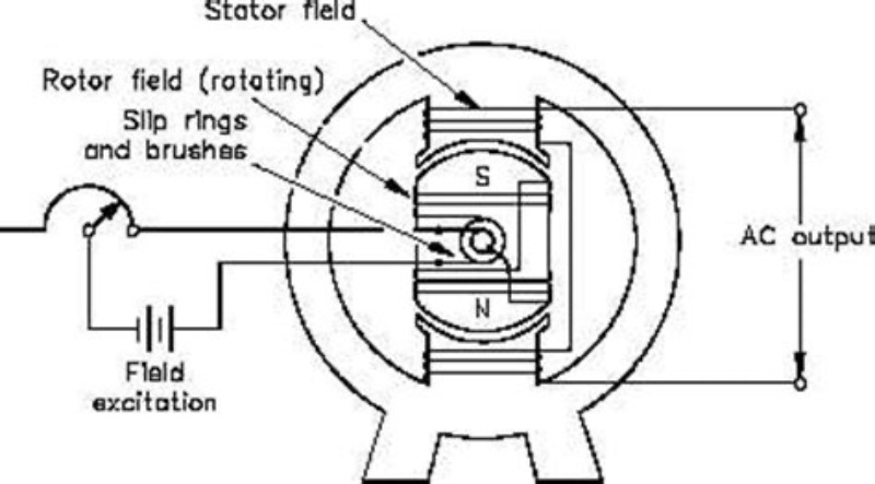
To explain how AC electricity is made we need to go back to our dam. The generators run at a fixed RPM making alternating current at 60 cycles a second or 60 hertz. Power is created when two magnetic fields pass through one another cutting lines of flux. The one fixed is called the stator and the one rotating is the rotor. Every time the north pole magnet passes by the other north pole magnet it makes a spike of electricity. When the south pole goes by it makes a spike of electricity in the opposite direction creating alternating current. The rotor is an electromagnetic field and by adjusting the power to the field you can adjust the amount of power coming out of the stator windings. It is how all generators. the alternator on your engine is not too much different with the exception of a series of diodes athe only allow the current to flow in one direction making DC current.
Induction is the means by which the energy is passed into a coil of wires or windings wrapped around an iron core magnet. And the electricity is then passed down the wires and in to the grid.
Induction of AC or alternating field current can be used to pass a very high voltage from one coil of wires or windings to smaller set of windings to make a lower voltage. Stepping down the voltage using a series of transformers one at a time until power reaches your dock at the right voltage. You can use the same process to increase the voltage if need be.
What actually gets to your boat is called single phase electricity. Pulling power from only one phase line and stepping it down to 240 Volts 50 Amps or 120 Volts 30 Amps that is used to supply the docks and your boat.
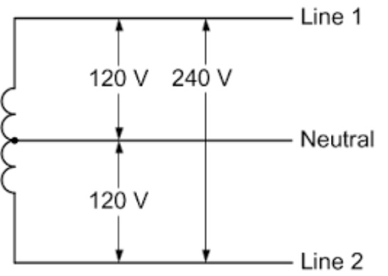
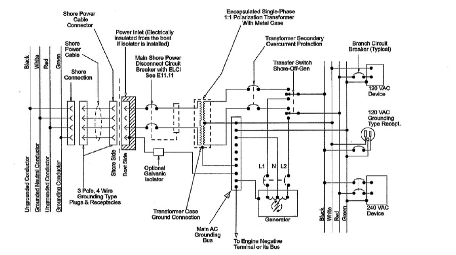
Line voltage is always incoming power and is represented by L-1, L-2, N Neutral and G for Ground.
Transformers can change Voltage up or down. And by putting in a what’s called a tap in the coil of wire or windings we can split the voltage and take power out of the middle of the windings. Giving us two voltages to work with from the same power source called split phase.
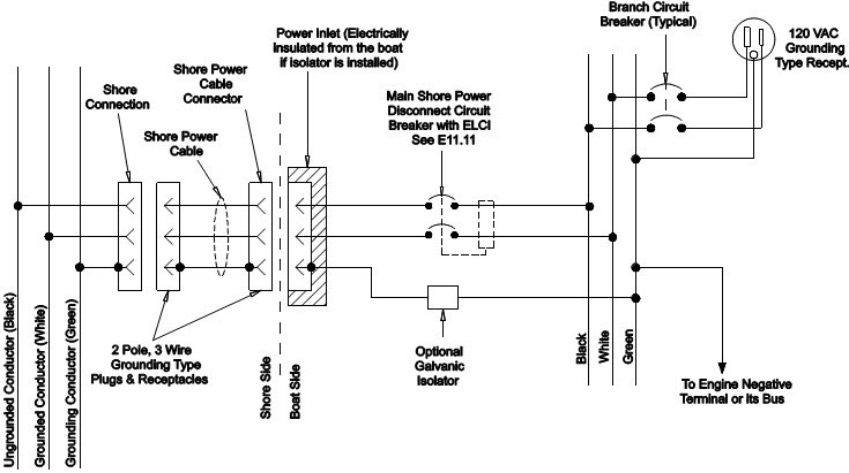
On a boat with 240 Volt 50 Amp inlet you would be receiving L-1 Black and L-2 Red Neutral White and a Green ground wire.
On a boat with 120 volt 30 Amps of power you will receive L-1 black Neutral White and Green ground.
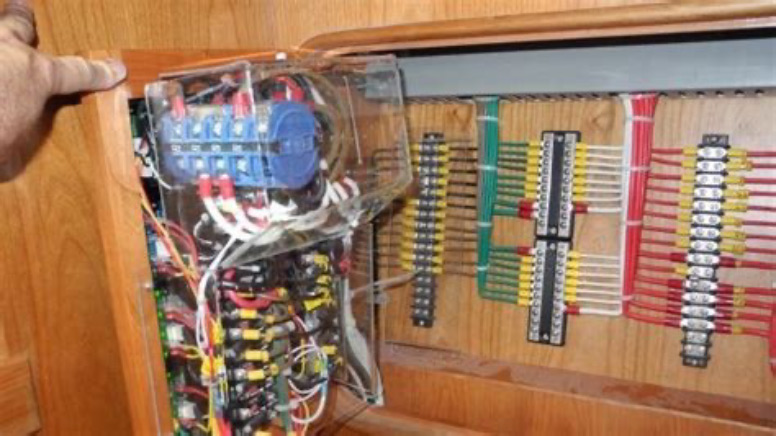
These three parts of your boats electrical system should be easily identifiable in your boats AC panel as main bus bars with all the distribution wire coming back to the source of power.
There are typically three main AC power sources on a vessel. One being the shore power two the generator and three an inverter or more typically inverter/charger. Switching between shore power and a generator is typically done through a power selector switch located on or near the AC panel. Called a break before make switch, it completely disconnects a boat from one power source before connecting to a new power source.
A well installed electrical system should be well labeled easy to use and understand once a boat owner becomes familiar with how the boat is set up

